Easy Driver Pinout is There a Shield for the Easydriver Board
EASYDRIVER: 4-Wire-Stepper Motor Driver
Brian Schmalz Design on A3967 IC — Bi-Polar Motors — .75A@30v peak — Making Using This a Breeze! Ardu_Serie#48
Hi, this post is part of my study of motor drivers on the hobbyist's market. This time we will analyze EasyDriver : An Open Source Hardware Stepper Motor Driver.
                      In this                                      overview                                      we will see:                                            What                                      problem                                      do we deal with;
Quick                                      pinout                                      description of ED board;
                                      First attempts                                      of Arduino's codes and
                                      How to Use                                      ED :) and not                        killing it            :/
                                      Quick notes                                      about EasyDriver 4.4 (ED) w/            Brian's advices              \o/
What problems do we deal with:
- Stepping motors are more complex than two-wire motors; there is the issue of the coils and the combination of their ends;
- We need a low-cost solution to drive stepper motors; the industrial motor driver is very costly;
- There are others ASIC Device on the market (ie UCN5804B, TLC5940, VNH2SP30, Allegro A3967 ) to choose from (see this post on this link);
- Breadboarding connections would be precarious for driving motor; I already killed one EasyDriver, two Adafruit v1, and v2 boards (see quick notes below).
- We need fine current control for the stepper motors; Arduino cannot withstand above 40mA per pin; a minimally decent stepper motor needs to run in the house of one ampere, at least …
- We need a fine control of the various phases and modes that we spin step motors, and on-the-fly :)
Let's begin…
The Easy Driver is basically just a breakout board for this driver chip, A3967, so the datasheet is your best source of information about how it all works.
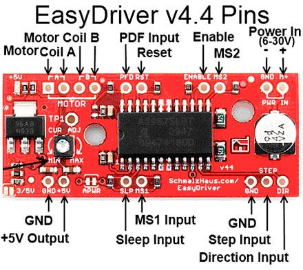
However, if all you need is a reference to the pins, here you go:
- GND: There are three GND (Ground) pins on the Easy Driver. They are all connected together inside the board. Connect the negative side of your power supply, as well as from any other boards you are using to drive the Easy Driver to one or more of the GND pins;
- M+: This is the power input to the EasyDriver. Connect this to the positive power supply lead. This should be a 6V to 30V, 2A (or more) power supply that is clean (low ripple);
- A and B : (four pins) These are the motor connections. See below diagrams for how to hook these up. A and B are the two coils of the motor and can swap the two wires for a given coil (it will just reverse the direction of the motor). Make CERTAIN that this connection to the motor is solid, and NOT through a connector that has any chance of intermittent contact (which will fry the motor driver chip);
- STEP: This needs to be a 0V to 5V (or 0V to 3.3V if you've set your Easy Driver that way) digital signal. Each rising edge of this signal will cause one step (or microstep) to be taken;
- DIR (Direction): This needs to be a 0V to 5V (or 0V to 3.3V if you've set your Easy Driver up that way) digital signal. The level if this signal (high/low) is sampled on each rising edge of STEP to determine which direction to take the step (or microstep).That's it — those are the only signals that you absolutely need to connect to anything. All the rest below are optional — in other words, the Easy Driver sets them to reasonable default values.
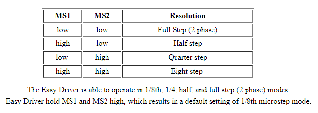
- MS1/MS2: These digital inputs control the microstepping mode. Possible settings are (MS1/MS2) : full step (0,0), half step (1,0), 1/4 step (0,1), and 1/8 step (1,1 : default);
- RST (reset): This normally high input signal will reset the internal translator and disable all output drivers when pulled low;
- SLP (sleep): This normally high input signal will minimize power consumption by disabling internal circuitry and the output drivers when pulled low;
- ENABLE: This normally low input signal will disable all outputs when pulled high;
- PFD: This one is complicated — please see the datasheet for more information. We default it to slow decay mode, but you can override with your own voltage on this pin. (or by populating R17);
- +5V: You see that the EasyDriver has a pin labeled 5V. What is it for? Well, there is a lot of confusion about this pin. It is NOT for powering the Easy Driver at 5V. In other words, it is NOT a power input or input of any kind. In fact, it's an output pin! Yup, the EasyDriver's 5V regulator has some extra juice, and so we brought out the 5V output of the regulator for you to use if you want. This means that you can connect other things to this pin that need 5V to operate, and the EasyDriver will power them. To a limit, of course. So, his is an OUTPUT pin that will provide either 5V (default) or 3.3V from the voltage regulator, at a small amount of current (say 50mA — depends on input voltage) to power a circuit that you may need power. If you cut jumper APWR (SJ1) then you can use the 5V pin as a VCC input to the Easy Driver, powering it with your own VCC supply;
- 3/5V JUMPER: What do this jumper do on the board? The way I designed the EasyDriver is with a power supply that can supply either 3.3V or 5V to the EasyDriver's logic-level power rail (Vcc on the schematic). This allows people to use the Easy Driver with a microcontroller that output either 3.3V or 5V control signals;
- APWR: The purpose of APWR is to allow users to disconnect the built-in logic power supply of the EasyDriver and power it using their own 5V or 3.3V logic level power supply. You might want to do this for power savings reasons. For example, if you're using a 24V M+ motor power supply for the EasyDriver, the built-in voltage regulator (IC2 on the schematic) will get very hot because it's dropping that 24V down to 5V and giving up all of that extra voltage as heat. This is very inefficient and will raise the temperature of the board;
LAB & Code
What hardware/software can I use to test my EasyDriver?
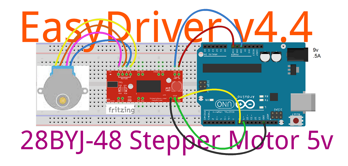
Here's what I do. I solder headers in the pins of the EasyDriver and put it into a breadboard. I put the wires on my stepper motor to a 4-pin .100" male header and plug that into the breadboard so it connects properly to the EasyDriver. Then I take a PC power supply and use the 9V (.5A) from that into the Arduino Power DC Jack P4 2.1mm Female J4 and GND and M+ pins on the EasyDriver. Then I tie the DIR to pin 8 with a wire. Then I take a square wave with a frequency of about 500Hz from Arduino pin 9 and put it into the STEP pin. This I generate with a signal generator or an Arduino UNO. The motor should be spinning at this point. You can then take the DIR pin and write HIGH to see the motor go in the other direction. As the motor is running, you can slowly adjust the current adjust pot to see the effect that it has on the smoothness of the motor's motion (video above and notes below:)
Some Example of Coil Resistance / DC Resistance (in descending order):
28BYJ-48 High-Quality Stepper Motor 12V→ DC resistance : 500Ω±2%(25℃)
28BYJ-48 High-Quality Stepper Motor 12V→ DC resistance : 200Ω±7%(25℃)
28BYJ-48 Series — 5V Stepper Motor → Coil Resistance: 50Ω±7% → also known as DC resistance 50Ω±7%(25℃)
High Precision 42X34mm 0.4A 12V Bipolar Stepper Motor 1.8 NEMA 17 →Resistance per phase = 30 Ω±10%
Motor de Passo NEMA 17–3,5 kgf.cm / 0,4A — Wotiom → Resistência por Fase: 20Ω ±10%
QUICK NOTES ABOUT EASYDRIVE: - Brian Schmalz, the EasyDriver designer, is very knowledgeable and courteous; Excellent support in his website; - The most likely cause of problems with killing EasyDrivers has always been bad wiring - either between the power supply and the ED or between the ED and the motor. It's critical that these connections are never broken while under power. Also shorts between motor coil wires must be avoided; (answered by Brian Schmalz via email) - The motors I was using :/before killing my ED board:/ are not good ones for use with the Easy Driver. It's coil resistance is too high (as indicated by the rating of 12V). So I should look for another and find some motors with 2 to 4V coils to be driven by the ED to have better performance with microstepping. (Brian Schmalz's advice); - T his battery is probably fine; at first I thought that 1500mah would be too much amperage. but Brian said that this would be a good battery. the problem is the battery connections with the ED or the ED with the motor; - My project can be nicely driven either by H-bridge chips like the L293D, or by more feature-rich motor drivers like the EasyDriver or both together; - ED: It works well. Easy to use with literally any microcontroller you can imagine. I use mine with a 5v Arduino UNO; - Just beware of EMI. The A/B pads and traces leading to them, along with those pins on the chip, and your cabling leading to the stepper motor, will throw off a ton of EMI. This is not a fault of the board, it's just what happens when you switch a stepper motor. It can mess with nearby microcontrollers and ICs. So be careful how you lay out your project - put some distance between the EasyDriver + stepper motor and other components if you can. If you can't keep them isolated by distance, shield sensitive components with conductive, grounded material; - The chip can get hot to the touch. Please considering adding a heat sink to the top of the chip; - Overall, ED worth the price; - ED: This is so easy to use. With the example code from the Brian's website, it is very straight forward on how to use this driver; - It does get very warm. But if you use the sleep mode when the motor does not need to be on, the driver board has time too cool down; - Works great, but chip get hot at .5 amp. If you need more ampere you can bought the larger, slightly more expensive, Big Easy Driver version(2 amp amp), and solve your heating problems once and for all! - If you don't intent to change the micro-step options on the fly so maybe you should hard wired those and just used the direction and step controls can be a good option; - These will get warm, even hot in some cases. The chip is syncing a lot of power and that shows through heat. If you are running this on the higher end of the spec, it is suggested that you manage the heat with a heat sink on the chip; - There's a great library that you can use for these called the AccelStepper library. It incorporates acceleration and deceleration quite easily; - Programming it is a snap using the AccelStepper library; - We suggest everyone should at least glance at the Atmel manual for the Arduino chip an try using some registers directly or use chipKIT uC32: Basic Microcontroller Board with Uno R3 Headers; - If you are in a hurry to just make things work this really is a great simple driver. Make sure to take time to adjust the current limit for your motor using the test point before plugging the motor in - there is a voltage to current formula in the manual. For low cost this is very useful; - It puts out a lot of heat, if you're using a motor to its full capability, consider a fan when mounting these somewhere; - The pot is super small, watch out when turning it with a metal screw driver; it can slip:/ - watch out to not touched the capacitors beneath it, it can spark and the chip would stop working; - Works as advertised, easy to use, just follow Sparkfun guides on the product webpage; - Make sure to head their note asking you to not connect/disconnect the motor while the driver is on; this will kill your EasyDriver so don't do it! - Do not loosely wired your motor to the board; it could came off during testing and your driver are died; - works great when you use it correctly… Easy to blow when you don't use it correctly (see my video); - There was a catastrophe: one of my boards got killed so I had to improve the soldering and study this board even more; - I did blow one up , but it so cheap; It was a no brainer to replace than to fix it; - Purchased two boards anticipating; In case of you burn the first one ;) - made sure to solder proper terminals to the driver; I published this video demo to help you out;) - It may take a little experimentation to get the windings connected correctly (this post may help you in discover it [LINK HERE!]). If the motor misses or runs rough reverse the winding pairs until proper operation. The advantage of operating as a bipolar motor is direction can be reversed simply by swapping the wire pairs. That doesn't apply in unipolar mode; (Lewis Loflin) - The board works well and easy to program for;- After running full rotations and near high speed the chip gets extremely hot and the motor can starts acting jerky. Probably a heat sink will solve that;
- Very simple to use following Sparkfun's hook-up guide; Works as promised; - Like all of the boards from sparkfun it was very well built; - Lots of options so it nice to have around so when you need to throw a project together is a good choice; - The central IC does get very hot. Technician would recommend putting it in sleep mode whenever you can; (Above adapted from Sparkfun page) - The EasyDriver can supplies enough current to drive the L298N which is a few milliamps at most and no calibration is required. If using ED to drive the L298 be certain to connect the motor voltage on Easy Driver to 5 volts or you will blow the L298N; (Lewis Loflin) - Minimum Delay Between Steps: 2s - With bipollar stepper motor if you don't have enough delay between the steps the motor will stall; this is an electrical device ... there's inductance envolve here ... if there isn't a little bit of delay and if you try to switch it so fast, it will just stall; (Lewis Loflin)
Well, hopefully, this post has given you a solid understanding…or not that much :/… on how the EasyDriver stepper motor works (I think you guys get the idea, at least:)
So where do we go from here?
DRV8825 — Stepper Motor Driver Carrier, High Current.
Bye for now!
Credits & References:
Brian Schmalz
Easy Driver Hook-up Guide
28BYJ-48 Stepper Motor and ULN2003 Driver Intro
28BYJ-48 Stepper Motor Disassembly
A3967 Datasheet
Stepper motor interfacing with Microcontrollers tutorial
The Maker Show: Episode 8 — Driving Your Stepper Motor with an Arduino
Download All Files For This Project
Videos for this Article:
EasyDriver — Stepper Motor Driver — LAB 01 — Ardu_Serie # 48
Soldering EasyDriver's Pin — Ardu_Serie#48
EASYDRIVER PINOUT: Brian Schmalz — A3967 IC — Bi-Polar Motors — .75A@30v peak
Soldering EasyDriver v4.4 — Improved Technical Soldering
Related Posts:
Meet DoRobot — Assembly Techniques J3 Caterpillar-Crawler-Chassis v 1.0 — ArduSerie#46
L 9100S — Toy Driver Easy To Use — Toy-low-voltage-h-bridge-easy-to-use-motor — .8A@12v peak — Ardu_Serie#47
E ASYDRIVER: 4-Wire-Stepper Motor Driver — Brian Schmalz Design on A3967 IC — Bi-Polar Motors — .75A@30v peak — Making Using These a Breeze! Ardu_Serie#48
D RV8825 — High Current Stepper Motor Driver Carrier — Stepper Motor — Bipolar Mode — 2.5A@45v peak — Ardu_Serie #59
L 298N — Dual Full-Bridge Driver — Darlington Transistor Arrays Based — 3A@50v peak — Ardu-Serie#52
T B6612FNG: Dual DC Motor Driver — SparkFun Motor Driver — 3.2A@13.5v peak — Ardu-Serie#49
A 4988 — Stepper Motor Driver Carrier — Allegro's A4988 — Bipolar Stepper Motor Driver — 2A@35v peak — Ardu-Serie#53
A dafruit Motor Shield v1 & v2–4 DC Motors or 2 Stepper Motor or 2 Servos — 1.2A@25v & 3.2A@15v peak — Ardu-Serie#54
I FR 520 MOS — Module + DoRobot — Switch Heavy DC Loads — 10A@100v peak — Ardu-Serie#60
L 9110 H-bridge module + DoRobot — DC Stepper Motor Driver Board — .8A@12 v peak — Ardu_Serie#62
B TS7960B- High Current PN Half Bridge — High Current Motor Drive Applications — NovalithIC T M — 43A@24v peak — ArduSerie#64
V NH2SP30 — Monster Moto Shield — Use This Board In Extreme High-Demand Application — Full-Bridge Motor Drivers — 30A@16v peak — 30 Ardu_Serie#63
Source: https://medium.com/jungletronics/easydriver-4-wire-stepper-motor-driver-9f32b233efe6
0 Response to "Easy Driver Pinout is There a Shield for the Easydriver Board"
Post a Comment